This guide nails down the process, materials, equipment, defects, etc. of metal injection molding. Scroll down to get more details.
Introduction
Metal Injection Molding (MIM) is a combination of metal metallurgy and plastic injection molding. It combines the precision of injection molding with the strength and durability of metal materials and has been widely applied across industries such as automotive, aerospace, consumer electronics, etc. Today, let’s nail it down together within one article.
Definition of Metal Injection Molding (MIM)
Metal Injection Molding (MIM) is an advanced manufacturing process that combines the versatility of plastic injection molding with the strength and integrity of powdered metallurgy.
It involves blending fine metal powders with a binder material to create a feedstock suitable for injection molding.
This process allows for the mass production of complex metal parts with high precision and excellent mechanical properties, making it ideal for industries such as automotive, medical, aerospace, and electronics.

Source: kenenghardware.com
Process of Metal Injection Molding (MIM)
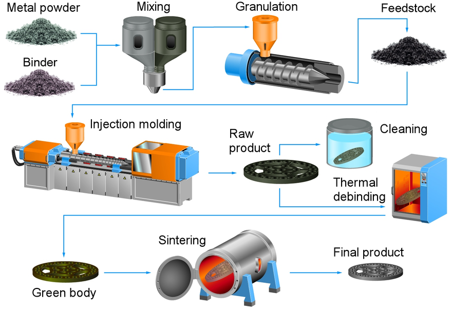
Source: wikipedia.org
Raw Material Selecting and Monitoring
The first step involves selecting high-quality metal powders that meet specific chemical and physical properties. Common materials include stainless steel, titanium alloys, and nickel-based superalloys. The powders typically have a particle size of less than 20 micrometers to ensure uniform mixing and optimal sintering. Rigorous monitoring is essential to maintain consistency in particle size distribution, purity, and morphology.
Material Mixing
Selected metal powders are thoroughly mixed with a thermoplastic binder system to create a homogeneous feedstock. The binder usually consists of polymers, waxes, and additives that aid in the molding process. Precise control of the powder-to-binder ratio is crucial to achieve the desired flow characteristics and mechanical properties in the final product.
Mixture Granulation
The homogeneous mixture is then cooled and granulated into pellets, forming the feedstock for injection molding. Granulation ensures uniformity in particle size, which is essential for consistent feeding and melting behavior during the molding process.
Injection Molding
The feedstock pellets are fed into an injection molding machine equipped with a specially designed screw and barrel to handle metal powders. The material is heated until the binder melts, allowing the mixture to flow. Under high pressure, the molten feedstock is injected into a mold cavity shaped like the desired part. After cooling, the molded piece, known as the “green body,” is ejected from the mold.
Solvent or Catalytic Debinding
The green parts contain a significant amount of binder that needs to be removed. In solvent debinding, parts are immersed in a solvent bath that dissolves the soluble components of the binder. In catalytic debinding, a catalyst is used to decompose the binder chemically. This step reduces the binder content without disturbing the part’s geometry, resulting in a “brown part.”
Thermal Debinding
The brown parts undergo thermal debinding, where they are slowly heated in a controlled atmosphere furnace to remove the remaining binder through thermal decomposition. This step must be carefully managed to prevent defects such as cracking or warping due to rapid binder removal.
Sintering
After debinding, the parts are sintered at temperatures ranging from 1,200°C to 1,450°C, depending on the material. Sintering occurs in a controlled atmosphere to prevent oxidation. During this phase, metal particles fuse together, significantly reducing porosity and causing the part to shrink by 15-20%. The result is a dense, solid metal component with mechanical properties comparable to wrought materials.
Secondary Operations (HIP, machining, heat treating, grinding, etc.)
Depending on the application’s requirements, secondary operations may be performed:
-
Hot Isostatic Pressing (HIP): Applies high pressure and temperature uniformly to eliminate residual porosity and enhance mechanical properties.
-
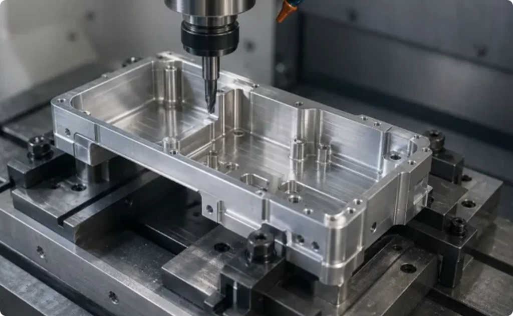
Machining: Used for achieving tighter tolerances or adding features not possible during molding.
-
Heat Treating: Alters the microstructure to improve hardness, strength, or toughness.
-
Grinding and Polishing: Enhances surface finish and dimensional accuracy.
Inspection and Packaging
Finished parts undergo rigorous inspections to ensure they meet all specifications:
-
Dimensional Inspection: Using tools like calipers, micrometers, and CMM machines.
-
Mechanical Testing: Assessing properties such as tensile strength, hardness, and elongation.
-
Non-Destructive Testing: Techniques like X-ray or ultrasonic testing to detect internal defects. Once verified, parts are cleaned, packaged appropriately to prevent damage or contamination, and prepared for shipment.
To clarify the inputs and outputs of each step in the process, we have drawn a table to help you have a better understanding.
|
Process step |
Process input |
Process output |
|---|---|---|
|
Mixing |
Powder and binder |
Powder/binder mixture |
|
Granulation |
Powder/binder mixture |
Feedstock |
|
Molding |
Feedstock |
Green part |
|
Debinding |
Green part |
Brown part |
|
Sintering |
Brown part |
Finished part* |
*May require secondary operations
Process Input and Output Products in the MIM
Materials Used in Metal Injection Molding (MIM)
A wide range of metals and alloys can be processed using MIM, offering designers flexibility in material selection. Apart from the metal powder used, binders are also essential. The combination of the two allows for the production of complex, high-precision metal components with excellent performance.
1. Metal Powders Used in MIM
|
Metal Category |
Examples |
Key Properties |
Applications |
|---|---|---|---|
|
Stainless Steels |
Corrosion resistance, high strength |
Surgical tools, automotive, marine equipment |
|
|
Low-Alloy Steels |
Fe2Ni, Fe4Ni |
Good strength, machinability |
Automotive parts, gears, fasteners |
|
Tool Steels |
M2, D2 |
High hardness, wear resistance |
Cutting tools, molds, dies |
|
Titanium Alloys |
Ti-6Al-4V |
High strength-to-weight ratio, biocompatibility |
Aerospace, medical implants, high-performance parts |
|
Superalloys |
Inconel 718, Hastelloy |
High-temperature strength, corrosion resistance |
Aerospace engines, turbines, chemical processing |
|
Copper Alloys |
Copper (Cu), Bronze, Brass |
Excellent electrical and thermal conductivity |
Electrical connectors, heat exchangers |
|
Tungsten Heavy Alloy |
Tungsten-Nickel-Iron Alloys |
High density, excellent mechanical strength and toughness |
Medical radiation shielding, |
|
Tungsten Carbide-Cobalt (WC-Co) |
Tungsten Carbide-Cobalt (WC-Co) |
Extreme hardness |
Mining drilling and excavation tools, |
|
Other Metal Powders |
Nickel Alloys, Cobalt-Chromium |
High-temperature and wear resistance |
High-temp applications, medical implants |
2. Binders Used in MIM
|
Binder Component |
Common Material Examples |
Function |
|---|---|---|
|
Main Binder |
Polypropylene (PP) |
Provides flowability and shape retention during molding. Widely used for its ease of processing. |
|
|
Polyethylene (PE) |
Similar to PP, it adds flexibility and durability during the molding process. |
|
|
Polystyrene (PS) |
Adds rigidity to the feedstock and improves its mold-filling ability. |
|
|
Paraffin Wax |
Lowers the viscosity of the feedstock, improving flow and mold-filling during injection. |
|
Secondary Binder |
Stearic Acid |
Aids in binder removal during debinding; acts as a lubricant during the molding process. |
|
|
Polyethylene Glycol (PEG) |
Water-soluble, used in solvent debinding processes to partially remove the binder. |
|
|
Carnauba Wax |
Helps in solvent-based debinding, providing early-stage binder removal. |
|
|
Microcrystalline Wax |
Provides part stability during debinding and can be easily thermally decomposed. |
It is noted that metal powders make up around 60-65% of the feedstock volume, while the binder comprises the remaining 35-40%.
This composition ensures adequate flow properties while maintaining the necessary amount of metal content for a dense, strong final product after sintering.
Equipment Used in Metal Injection Molding (MIM)
Specialized equipment is essential for each stage of the MIM process:
-
Mixers: For homogeneous mixing of metal powders and binders.
-
Granulators: To produce uniform feedstock pellets.
-
Injection Molding Machines: Modified to handle abrasive metal feedstock with hardened screws and barrels.
-
Debinding Furnaces: Designed for precise temperature control and atmosphere management during binder removal.
-
Sintering Furnaces: Capable of reaching high temperatures with controlled atmospheres (vacuum, inert gas, hydrogen).
-
Secondary Operation Tools: CNC machines, grinders, heat treatment furnaces.
-
Inspection Equipment: Coordinate measuring machines (CMM), hardness testers, microscopes, and non-destructive testing apparatus.
Parameters in Metal Injection Molding (MIM)
From material selection to final inspection, each stage must be precisely controlled to meet mechanical and dimensional requirements and ensure high-quality parts. Next, let’s explore the parameters involved in each step in detail.
|
Step |
Parameter |
Description |
|---|---|---|
|
Powder Selection |
Powder Chemistry |
Chemical composition of metal powder, affecting material properties. |
|
|
Powder size & distribution |
Particle size (2-20 microns) impacts flowability and sintering behavior. |
|
Granulation |
Feedstock Density (Pycnometer, Archimedes) |
Measures metal content and powder loading, affecting flow and shrinkage. |
|
|
Feedstock viscosity |
Resistance to flow during injection; impacts mold filling and shape retention. |
|
Injection Molding |
Component mass |
Weight of green part; indicates proper mold filling and uniformity. |
|
Debinding |
Weight loss |
Binder removal process; weight loss indicates how much binder is removed. |
|
Sintering |
Component dimensions |
Measures shrinkage; ensures final part meets dimensional tolerances. |
|
|
Component mass |
Confirms proper densification and absence of internal porosity. |
|
|
Component density |
Density post-sintering; indicates mechanical properties like strength. |
|
|
Chemistry analysis |
Checks for contamination or chemical changes after sintering. |
|
|
X-ray |
Non-destructive testing for internal defects like voids or cracks. |
|
|
Crack detection |
Detects surface/internal cracks through DPI, ultrasonic, or MPI methods. |
|
|
Microstructure |
Analyzes grain size and phase distribution to assess material quality. |
|
|
Mechanical testing |
Evaluates strength, hardness, and toughness of the final part. |
Common Defects in Metal Injection Molding (MIM)
In Metal Injection Molding (MIM), defects can arise despite careful control. Understanding these common issues, their causes, and solutions is key to ensuring high-quality parts. Let’s look at some frequent defects and how to address them.
|
Defect type |
Possible causes |
Remedies |
|---|---|---|
|
Flash |
Too high a pressure inside the die, poor flatness of mold surface along the parting line, venting channel too large |
Use large tonnage machine, proper tool making, use a lower injection speed and molding pressure, optimize the switch point |
|
Sticking in cavity |
Too high a molding pressure, not enough thermal shrinkage, early ejection, improper mold design or making |
Use a lower injection speed, molding/holding pressure, and mold temperature, increase cooling time, eliminate undercut and increase draft angle, adjust ejection area and location, redesign the binder |
|
Sink mark |
Thermal shrinkage, low density |
Increase molding/holding pressure and injection speed, decrease mold temperature, increase gate area, add venting channels, decrease speed when passing thick sections |
|
Voids |
Trapped gas, absorbed moisture |
Increase holding pressure, decrease injection speed, increase mold temperature, increase gate area, move gate to thick sections |
|
Burn marks |
Overly heated binders |
Decrease injection speed and feedstock temperature, increase gate area, change gate location |
|
Weld lines |
Cold feedstock in the die |
Increase injection speed, mold temperature, and feedstock temperature, enlarge gate opening, add venting channels or overflow wells near weld line locations, move gate location, redesign parts to avoid stream partition |
|
Flow mark |
Cold feedstock in the die |
Increase injection speed, mold temperature, and feedstock temperature, enlarge gate opening, change gate location |
Advantages of Metal Injection Molding (MIM)
-
Design Flexibility: Ability to produce complex geometries not feasible with traditional methods.
-
Material Efficiency: Minimal waste compared to subtractive processes.
-
High Mechanical Properties: Comparable to wrought materials after sintering.
-
Cost-Effective for High Volumes: Economical for producing large quantities of small, intricate parts.
-
Consistent Quality: Automated processes ensure repeatability and tight tolerances.
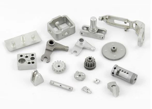
Applications of Metal Injection Molding (MIM)
MIM is utilized across various industries:
-
Automotive: Gears, turbocharger components, and fuel system parts.

Metal Injection Auto Parts
Source: porite.com -
Medical Devices: Surgical instruments, orthodontic brackets, and implants.

MIM Stainless Steel Jaws
Source: pim-international.com
-
Consumer Electronics: Connectors, heatsinks, and smartphone components.

MIM Consumer Electronics Parts
Source: inmettech.com -
Aerospace: Fuel nozzles, sensor housings, and fasteners.

MIM Low Alloy Steel Seat Belt Component
Source: pim-international.com -
Firearms and Defense: Triggers, sights, and small precision components.