A DFM checklist for 3D printed and CNC machined parts to help engineering teams review geometry, tolerances, material suitability, post-processing impact, cost and lead-time risks, and other key considerations before manufacturing.
Introduction
In today’s product development environment, engineering teams are expected to move faster while maintaining tighter control over quality, cost, and delivery timelines. Whether a company is building functional prototypes, validating product designs, preparing bridge production, or sourcing low-volume end-use parts, one factor consistently determines manufacturing success:
Design for Manufacturability, or DFM.
For 3D printed and CNC machined parts, DFM is not simply a technical review at the end of the design process. It is a practical engineering discipline that helps teams identify design risks before production begins. A well-executed DFM review can reduce unnecessary redesigns, prevent tolerance-related issues, improve part performance, shorten lead times, and avoid avoidable production costs.
Many companies invest heavily in CAD design, material selection, simulation, and product testing. Yet manufacturing issues often appear only after files are submitted for quoting or, worse, after parts are already in production. Common problems include unsupported thin walls, unrealistic tolerances, inaccessible CNC features, sharp internal corners, insufficient clearance, improper material assumptions, and surface finish requirements that are not aligned with the selected process.
This is why a structured DFM checklist is valuable. It gives engineering and procurement teams a repeatable way to evaluate whether a design is ready for additive manufacturing, CNC machining, or a combined manufacturing strategy.

Why DFM Matters for Both 3D Printing and CNC Machining
3D printing and CNC machining are often discussed as separate manufacturing technologies. In practice, they are frequently used together across the product development lifecycle.
3D printing is highly effective for complex geometries, lightweight structures, rapid iteration, internal channels, and parts that would be difficult or costly to machine. CNC machining, on the other hand, remains essential for high-precision components, tight tolerances, production-grade materials, smooth surface finishes, and parts requiring consistent mechanical performance.
However, each process has its own design rules.
A part that looks simple in CAD may be expensive or difficult to machine because of deep pockets, tight internal radii, thin walls, or limited tool access. A part that appears ideal for 3D printing may still fail a manufacturability review because of unsupported overhangs, excessive warping risk, trapped powder, weak orientation, or post-processing limitations.
The goal of DFM is not to restrict design freedom. The goal is to help engineering teams make better manufacturing decisions earlier.
A strong DFM review answers questions such as:
-
Can this geometry be produced reliably with the selected process?
-
Are the tolerances aligned with the functional requirements?
-
Is the material suitable for the application and manufacturing method?
-
Will post-processing affect dimensions, appearance, or performance?
-
Are there avoidable features that increase cost or lead time?
-
Can the design be inspected consistently after production?
For enterprise-level projects, these questions are not minor details. They directly affect launch schedules, supplier communication, part approval, and total project cost.
Key DFM Considerations for 3D Printed Parts
3D printing provides significant design flexibility, but it does not eliminate manufacturing constraints. Different technologies such as SLA, SLS, MJF, metal 3D printing, and other additive processes have different capabilities, limitations, and post-processing requirements.
A professional DFM review for 3D printed parts should begin with the intended application. Is the part for visual validation, functional testing, assembly verification, end-use performance, or low-volume production? The answer determines which process, material, and finishing method are appropriate.
For resin-based 3D printing, engineering teams should pay close attention to wall thickness, hollow structures, drainage holes, surface quality, and dimensional stability. Resin parts can deliver excellent detail and smooth surfaces, but they may not always be suitable for high-temperature, high-load, or long-term mechanical applications unless the material is carefully selected.
For nylon processes such as SLS or MJF, designers should consider powder removal, minimum feature size, part orientation, and surface texture. These technologies are often strong choices for functional prototypes, complex assemblies, clips, brackets, housings, and lightweight components.
For metal 3D printing, the DFM review becomes even more critical. Support strategy, thermal distortion, build orientation, residual stress, surface roughness, machining allowance, and post-processing requirements all influence final part quality. Metal additive parts may also require heat treatment, CNC finishing, support removal, polishing, or inspection depending on their application.
A 3D printing DFM checklist should typically review:
-
Minimum wall thickness and feature size
-
Unsupported overhangs and support requirements
-
Part orientation and anisotropic mechanical properties
-
Hollow sections, drainage holes, and powder removal paths
-
Dimensional tolerance expectations
-
Surface finish and post-processing requirements
-
Threaded features, inserts, and assembly interfaces
-
Risk of warping, shrinkage, or deformation
-
Material suitability for mechanical, thermal, and environmental conditions
-
Inspection requirements for critical features
The most important point is this: not every feature needs the same level of precision. Engineering teams should clearly define which features are critical to function and which are non-critical. This allows manufacturers to focus precision, inspection, and post-processing efforts where they matter most.
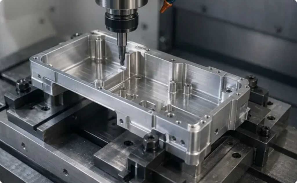
Key DFM Considerations for CNC Machined Parts
CNC machining is often selected when precision, repeatability, material performance, and surface quality are critical. It is widely used for aluminum, stainless steel, titanium, brass, copper, engineering plastics, and many other production-grade materials.
However, CNC machining is highly sensitive to geometry. A CAD model may be technically possible to machine, but still inefficient, costly, or risky if the design does not account for tooling, workholding, and machine access.
One of the most common DFM issues in CNC parts is overly tight tolerance specification. Many drawings apply tight tolerances across the entire part, even when only a few features are function-critical. This can increase cost and inspection time without improving product performance. A better approach is to apply tight tolerances only to critical interfaces, mating surfaces, sealing areas, bearing seats, and assembly features.
Another common issue is sharp internal corners. Because CNC tools are round, internal corners require a radius. Designers should avoid specifying sharp internal corners unless there is a functional reason, and they should define practical internal radii that match available tooling.
Deep pockets and thin walls also require special attention. Deep features may require longer tools, which can increase vibration, reduce accuracy, and affect surface finish. Thin walls may deform during machining or inspection. In many cases, small design adjustments can significantly improve manufacturability.
A CNC DFM checklist should typically review:
|
Review Item |
Key Notes |
|---|---|
|
Material Selection and Machinability |
Evaluate whether the selected material is suitable for CNC machining, considering hardness, strength, machinability, cost, and availability. |
|
Tool Access and Feature Accessibility |
Confirm that cutting tools can reach all required features without interference or excessive tool extension. |
|
Internal Corner Radii |
Avoid sharp internal corners. Add appropriate radii to match available cutting tools and reduce machining difficulty. |
|
Deep Pockets, Narrow Slots, and Long Holes |
Review features that may require long tools, special machining strategies, or additional operations, as they can increase cost and machining risk. |
|
Thin Walls and Deformation Risk |
Check whether thin walls may deform during machining, fixturing, or post-processing. |
|
Tolerance Strategy and GD&T Requirements |
Confirm whether tight tolerances and GD&T requirements are necessary, measurable, and achievable with the selected process. |
|
Thread Depth and Thread Accessibility |
Ensure threaded holes have sufficient depth, tool access, and manufacturable thread specifications. |
|
Surface Finish Specifications |
Define surface roughness and finish requirements clearly, such as as-machined, polished, bead blasted, anodized, plated, or painted. |
|
Datum Structure and Inspection References |
Confirm that datums, reference surfaces, and inspection points are clearly defined for manufacturing and quality control. |
|
Fixturing and Workholding Feasibility |
Evaluate whether the part can be securely held during machining without deformation, vibration, or access limitations. |
|
Secondary Operations and Post-Processing Requirements |
Review requirements such as anodizing, polishing, bead blasting, plating, painting, heat treatment, or assembly. |
|
Critical-to-Quality Features and Inspection Methods |
Identify key dimensions, functional surfaces, and critical features that require priority inspection or special measurement methods. |
For enterprise buyers, CNC DFM is not only about whether a part can be made. It is about whether it can be made consistently, inspected reliably, and delivered within the required timeline.
Choosing Between 3D Printing and CNC Machining
One of the most valuable outcomes of a DFM review is process selection. In many projects, the question is not simply “Can this part be 3D printed?” or “Can this part be CNC machined?” The better question is: Which process best supports the part’s function, timeline, material requirements, and cost target?
3D printing is often preferred when the design includes complex geometry, internal structures, low production volume, lightweight features, or fast design iteration. CNC machining is often preferred when the part requires tight tolerances, excellent surface finish, specific engineering materials, or high mechanical reliability.
In some cases, a hybrid approach is the best option. A part may be 3D printed for geometric complexity and then CNC machined on critical surfaces. This is especially relevant for metal parts, aerospace-style components, tooling, fixtures, and performance-driven engineering applications.
The DFM decision should be based on:
|
Decision Factor |
Description |
|---|---|
|
Part Function |
Determine whether the part is an appearance component, functional part, assembly component, or end-use part. |
|
Material Requirements |
Review whether the part requires metal, resin, nylon, engineering plastics, or specific alloys. |
|
Tolerance Requirements |
Confirm whether high-precision fits, sealing requirements, bearing features, or assembly tolerances are needed. |
|
Geometry Complexity |
Evaluate whether the part includes complex surfaces, internal channels, lightweight structures, or difficult-to-machine features. |
|
Production Volume |
Determine whether the requirement is for a single prototype, low-volume production, or more stable batch production. |
|
Lead Time |
Confirm whether fast delivery, rapid iteration, or a flexible production schedule is required. |
|
Surface Finish |
Review whether bead blasting, polishing, painting, anodizing, plating, or other surface treatments are needed. |
|
Assembly Requirements |
Determine whether the part must interface with other components, threads, inserts, fasteners, or assembly references. |
|
Inspection Needs |
Confirm whether dimensional inspection, material certification, quality reports, or special inspection methods are required. |
|
Total Cost of Production |
Evaluate the total cost impact, including manufacturing, post-processing, inspection, rework risk, and delivery requirements. |
A structured checklist helps teams make this decision with fewer assumptions and fewer surprises.
What Enterprise Engineering Teams Should Prepare Before Requesting a Quote
Before submitting files to a manufacturing partner, engineering teams can improve quoting accuracy and reduce back-and-forth communication by preparing a complete technical package.
At minimum, this should include:
|
Information Type |
Recommended Notes |
|---|---|
|
3D CAD Files |
Preferably provide STEP, STP, or native CAD files for accurate manufacturability review and quotation. |
|
2D Drawings |
Used to define critical dimensions, tolerances, threads, surface finish, and other technical requirements. |
|
Material Requirements |
Specify the required material, or indicate acceptable alternative materials if available. |
|
Surface Finish and Post-Processing Requirements |
Include requirements such as bead blasting, painting, anodizing, polishing, plating, dyeing, or heat treatment. |
|
Quantity and Expected Production Stage |
Indicate whether the project is for prototyping, functional testing, low-volume production, or another production stage. |
|
Application Context |
Help the manufacturer understand the part’s operating environment, functional requirements, and end-use conditions. |
|
Critical-to-Function Features |
Identify which areas, dimensions, or features are most critical to function, assembly, or quality. |
|
Assembly or Mating Part Requirements |
Explain how the part interfaces with other components and whether specific fit, alignment, or assembly requirements are needed. |
|
Inspection and Quality Requirements |
Specify whether dimensional reports, material certificates, quality inspection reports, FAI, or other documentation are required. |
|
Target Lead Time |
Provide the expected delivery timeline so the manufacturer can evaluate production scheduling and delivery options. |
When these details are missing, suppliers may quote based on assumptions. That can lead to price variation, production delays, or parts that do not meet the original engineering intent.
A strong DFM checklist helps teams organize this information before submission.
Download the DFM Checklist for 3D Printed & CNC Machined Parts
To help engineering, product development, and procurement teams review designs more efficiently, Unionfab has prepared a practical DFM Checklist for 3D Printed & CNC Machined Parts.
This checklist is designed to help teams evaluate key manufacturability factors before submitting parts for production, including geometry, material selection, tolerance strategy, surface finish, post-processing, inspection, and process selection.
Whether you are developing a functional prototype, validating a new product design, sourcing low-volume parts, or preparing for production, this checklist can help your team reduce avoidable manufacturing risks and communicate more effectively with your manufacturing partner.
Download the PDF checklist to review your design before production.
If you already have a project in progress, Unionfab’s engineering and manufacturing team can also support DFM review, process selection, material recommendations, and production planning for 3D printed and CNC machined parts.
Download the DFM Checklist and submit your project details to get professional manufacturing feedback.